Toyota BELTA 13A — OIL COOLER & TUBE (ATM)
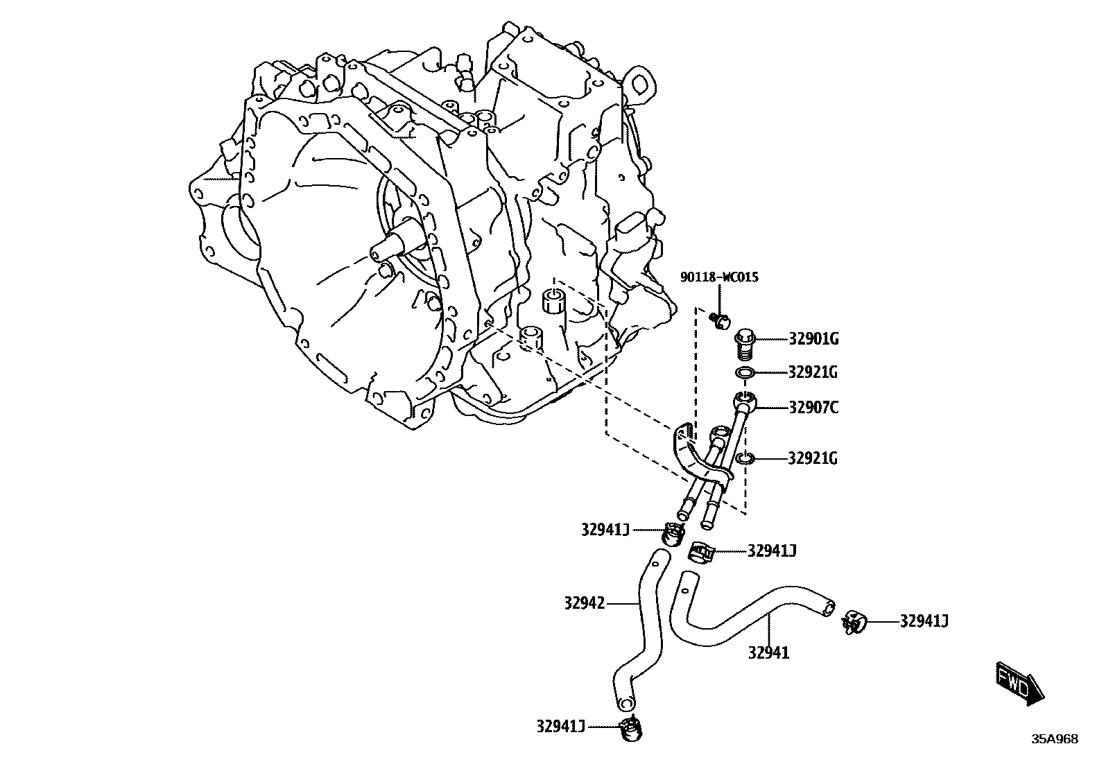
32901GBOLT, UNION(FOR OIL COOLER)
32907CTUBE SUB-ASSY, OIL COOLER W/O HOSE, NO.1
32921GRING, O(FOR OIL COOLER TUBE UNION)
32941JCLIP, NO.1(FOR OIL COOLER HOSE)
32942HOSE, OIL COOLER OUTLET, NO.1
90118WC015
7 parts on this diagram · 1 diagram in section
OIL COOLER & TUBE (ATM) for Toyota BELTA 13A
This section contains 7 genuine Toyota parts for the OIL COOLER & TUBE (ATM) system of the Toyota BELTA 13A. Key components include: BOLT, UNION(FOR OIL COOLER), TUBE SUB-ASSY, OIL COOLER W/O HOSE, NO.1, RING, O(FOR OIL COOLER TUBE UNION), HOSE, OIL COOLER INLET, NO.1, CLIP, NO.1(FOR OIL COOLER HOSE).