Toyota RUMION — OIL COOLER & TUBE (ATM)
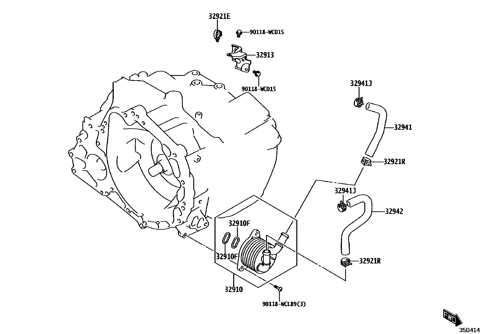
32910FRING, O(FOR OIL COOLER)
32913BRACKET, OIL COOLER
32921ECLAMP, HOSE(FOR OIL COOLER)
32921RCLIP, NO.2(FOR OIL COOLER HOSE)
32941JCLIP, NO.1(FOR OIL COOLER HOSE)
32942HOSE, OIL COOLER OUTLET, NO.1
90118WC015
90118WCL89
10 parts on this diagram · 1 diagram in section
OIL COOLER & TUBE (ATM) for Toyota RUMION
This section contains 10 genuine Toyota parts for the OIL COOLER & TUBE (ATM) system of the Toyota RUMION. Key components include: COOLER ASSY, OIL, RING, O(FOR OIL COOLER), BRACKET, OIL COOLER, CLAMP, HOSE(FOR OIL COOLER), CLIP, NO.2(FOR OIL COOLER HOSE).