OIL COOLER & TUBE (ATM)
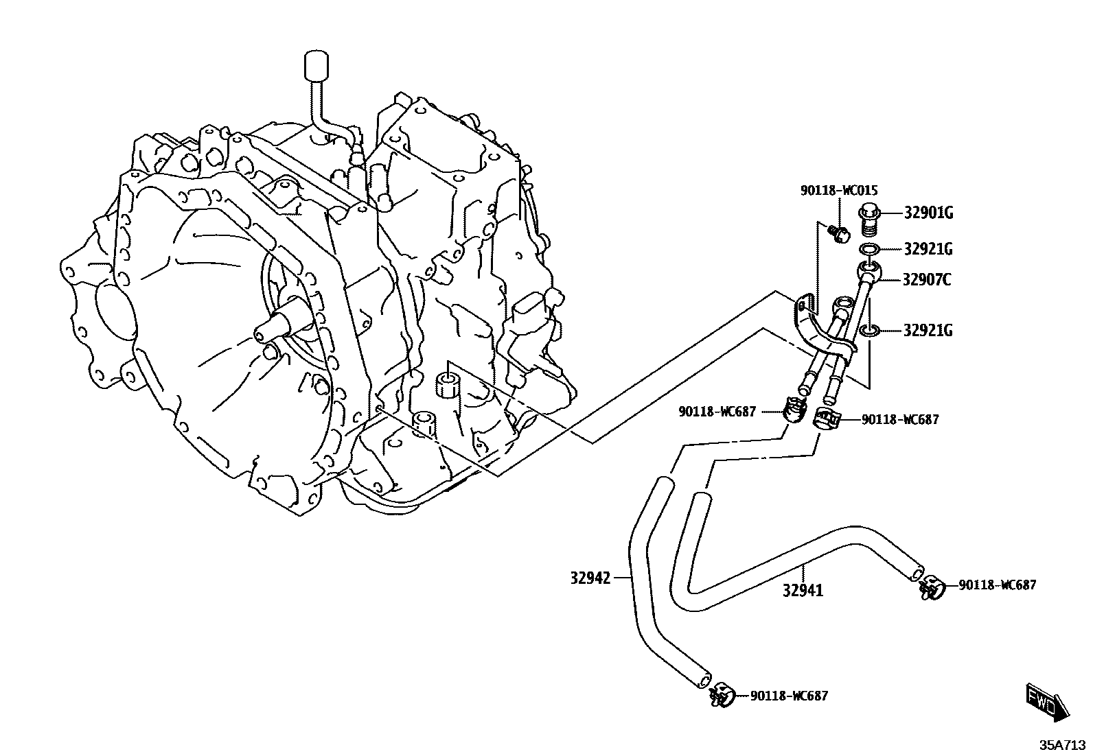
32901GBOLT, UNION(FOR OIL COOLER)
main90118-WC737×2iK14B..4FC..L..AFR; K14B..4FC..L..SA; K14B..4FC..L..SUD; K14B..4FC..P..AFR; K14B..4FC..P..SA; K14B..4FC..P..SUD; K14B..4FC..X..AFR; K14B..4FC..X..SA; K14B..4FC..X..SUD202007
POS.31; POS.32; POS.34; POS.39; POS.40; POS.41; POS.42; POS.44; POS.48; POS.49; POS.50; POS.52; POS.54; POS.56
32907CTUBE SUB-ASSY, OIL COOLER W/O HOSE, NO.1
main32904-WC001iK14B..4FC..L..AFR; K14B..4FC..L..SA; K14B..4FC..L..SUD; K14B..4FC..P..AFR; K14B..4FC..P..SA; K14B..4FC..P..SUD; K14B..4FC..X..AFR; K14B..4FC..X..SA; K14B..4FC..X..SUD202007
POS.31; POS.32; POS.34; POS.39; POS.40; POS.41; POS.42; POS.44; POS.48; POS.49; POS.50; POS.52; POS.54; POS.56
32921GRING, O(FOR OIL COOLER TUBE UNION)
main90118-WC736×4iK14B..4FC..L..AFR; K14B..4FC..L..SA; K14B..4FC..L..SUD; K14B..4FC..P..AFR; K14B..4FC..P..SA; K14B..4FC..P..SUD; K14B..4FC..X..AFR; K14B..4FC..X..SA; K14B..4FC..X..SUD202007
POS.31; POS.32; POS.34; POS.39; POS.40; POS.41; POS.42; POS.44; POS.48; POS.49; POS.50; POS.52; POS.54; POS.56
32941HOSE, OIL COOLER INLET, NO.1
main32941-WC002iK14B..4FC..L..AFR; K14B..4FC..L..SA; K14B..4FC..L..SUD; K14B..4FC..P..AFR; K14B..4FC..P..SA; K14B..4FC..P..SUD; K14B..4FC..X..AFR; K14B..4FC..X..SA; K14B..4FC..X..SUD202007
POS.31; POS.32; POS.34; POS.39; POS.40; POS.41; POS.42; POS.44; POS.48; POS.49; POS.50; POS.52; POS.54; POS.56
32942HOSE, OIL COOLER OUTLET, NO.1
main32942-WC002iK14B..4FC..L..AFR; K14B..4FC..L..SA; K14B..4FC..L..SUD; K14B..4FC..P..AFR; K14B..4FC..P..SA; K14B..4FC..P..SUD; K14B..4FC..X..AFR; K14B..4FC..X..SA; K14B..4FC..X..SUD202007
POS.31; POS.32; POS.34; POS.39; POS.40; POS.41; POS.42; POS.44; POS.48; POS.49; POS.50; POS.52; POS.54; POS.56
90118WC015
main90118-WC015
90118WC687
main90118-WC687
7 parts on this diagram · 1 diagram in section